Rasberry Pi was launched today with a big bang. There are already 44,161 followers on Twitter and the launch made to headline news in CNN.com, BBC and other news sites.
This credit card size little computer has been under development multiple years and is now available at $35 price point.
The price / performance ratio is pretty amazing and since it is running Linux operating system it should be pretty straightforward to port / run different ham radio applications on this tiny little computer.
I signed up on the waiting list - let's see how quickly the two distributors can ramp up. This initial batch of 10,000 units was sold in few minutes according to some websites.
73 de Mauri AG1LE
Wednesday, February 29, 2012
Wednesday, February 1, 2012
Antenna Experiments - Human Body Resonance Frequencies
Inspired by "Ionic Fluid Antenna" article by N9ZRT David Hatch I started wondering whether human body could be used as an antenna.
Using human body as an antenna would have multiple obvious benefits such as
![]() |
| Human body by Leonardo da Vinci |
- mobility - ham radio operator would have the antenna always with him / her
- low cost - no need to buy expensive materials
- small size - no additional wires or aluminum tubes to carry with you
It is a well known fact that human body contains ionic fluids and it both absorbs and emits electromagnetic signals. In medical field these human body properties are used for many different purposes such as diagnostic imaging or diathermy treatment.
For example MRI (magnetic resonance imaging) scanners send and receive RF signals at Larmor frequency. The frequency range depends on magnetic field strength of the scanner - proton ( 1H ) resonance frequency is 63 Mhz at 1.5 Tesla field strength typically used in MRI scanners designed for hospitals.
![]() |
| RF coil for body imaging |
In early part of my career I worked in medical imaging field and thus have some hands on experience working with MRI RF coils. Designing RF coils for different body parts is a challenging job. In order to obtain best possible signal-to-noise ratio the RF coils need to be close to the target. On the other hand RF field homogeneity is also important to create clinically acceptable MRI images. Human body couples with MRI RF coils so calibration and impedance tuning is important and is typically quick automated operation - many patients have difficult time staying still in the magnet for extended periods. Also, SAR (specific absorption rate) level (the RF energy absorbed by human body) must to comply with FDA regulations.
However, most hams don't have superconductive 1.5 Tesla magnets or MRI RF coils in their ham schacks so I wanted to explore some other means how to couple RF energy to human body, understand at what frequencies it would be resonant and how good of an antenna human body would be.
After reading several articles on this topic it became clear to me that human body resonates at multiple frequencies and these frequencies also depend on the environment. Human in free space vs. standing on the ground would have different RF characteristics like any normally used antenna.
![]() |
| WARNING: RF Safety |
I wanted to study this a bit further and do some measurements myself. I determined that by using the AIM UHF antenna analyzer (created by W5BIG Robert Clunn) I could safely measure my own resonance frequency. The power output of this excellent device is between 0.2 - 20 microwatts that is well below SAR limits (for mobile devices typically 2W / kg for whole body). Safety is obviously utmost important as I did not want to get RF burns or cause other tissue damage due to this experiment.
Coupling a coax transmission line to my body was the next problem. I created a simple coupling device by attaching two electrodes designed for a transcutaneous electrical nerve stimulation (TENS) machine to a 50 Ohm coaxial cable. The distance between electrodes was 16 inches and the coaxial feed point was in the middle.This distance allowed me to test different configurations in vertical and horizontal modes. Picture below shows the RF feeder device.
I analyzed first this RF feeder circuit itself. Hanging the feeder circuit in vertical position inside my ham shack I measured SWR and complex impedance magnitude over 1 - 999 Mhz frequency range. This gave me a baseline to compare how attaching the electrodes to my skin would change the resonance frequencies. The SWR was over 2.0 between 1 and 244 Mhz. The dip in SWR was centered around 252 Mhz corresponding to 46.8 inches wavelength. Given that the coupling circuit is essentially a half wave dipole with 16 inch length the velocity factor of TENS electrode material is 16 / 23.4 = 0.68. The SWR also dips below 2.0 around 860 Mhz.
The next step was to attach the electrodes on my skin while in supine position and run the same test again.
I changed the SWR scale to get more detailed view. This time there are 2 main dips in 65 Mhz (181.4 inches wavelength) and 112 Mhz (105.5 inches wavelength) frequencies. Also, in 600 Mhz range the SWR dips below 2.0. The prominent dip at 112 Mhz corresponds to 105.5 inches wavelength
This result corresponds to literature. Human-body resonances fall typically in the frequency range of 30 - 300 Mhz.
Looking at the SWR graph above 50 MHz ham band represents roughly 1:3 SWR ratio from impedance matching perspective. I also noticed that the graph changed as I moved my arms and legs. With some practice it is possible to shift the SWR minimum by about 2 MHz just by moving self.
The posting I did in eham.net has created a lot of discussion mostly focused on safety risks and RF burns. I want to emphasize that RF safety is utmost important and human body should not be exposed to RF signals. Even at small power levels RF can cause diathermic heating in tissues causing painful tissue damage.
The fact the human body resonates at multiple frequencies presents also a problem if one is exposed to strong RF fields (like standing in front of directional antenna with RF transmission on). The RF radiation may cause "hotspots" where induced currents are causing localized RF burns, even though the overall SAR limit is not exceeded.
Ionic fluid antennas may have some special applications but human body should not be used as an antenna.
So - it looks like traditional metal objects are far superior as antennas if the purpose is to effectively radiate the RF power and not to use it to generate heat.
73 Mauri AG1LE
![]() |
| Human body resonance |
Looking at the SWR graph above 50 MHz ham band represents roughly 1:3 SWR ratio from impedance matching perspective. I also noticed that the graph changed as I moved my arms and legs. With some practice it is possible to shift the SWR minimum by about 2 MHz just by moving self.
The posting I did in eham.net has created a lot of discussion mostly focused on safety risks and RF burns. I want to emphasize that RF safety is utmost important and human body should not be exposed to RF signals. Even at small power levels RF can cause diathermic heating in tissues causing painful tissue damage.
The fact the human body resonates at multiple frequencies presents also a problem if one is exposed to strong RF fields (like standing in front of directional antenna with RF transmission on). The RF radiation may cause "hotspots" where induced currents are causing localized RF burns, even though the overall SAR limit is not exceeded.
Ionic fluid antennas may have some special applications but human body should not be used as an antenna.
So - it looks like traditional metal objects are far superior as antennas if the purpose is to effectively radiate the RF power and not to use it to generate heat.
73 Mauri AG1LE
Sunday, January 29, 2012
Flex3000 revisited - new PC makes a huge difference
I have been running PowerSDR software for my Flex3000 on a Thinkpad T60 laptop computer for the last 12 months. While the setup has been working quite well the laptop is fairly slow and a bit under-powered for this purpose.
My next door neighbor was building a desktop PC and we were chatting the component choices he had made. I decided to build a brand new desktop PC and leverage the research that he had already done.
I ended up ordering the following components for this project:
I had two existing video displays so I connected one with HDMI cable and the other with VGA cable. The motherboard has built-in 2 display graphics chip with decent performance. It has also IEEE 1394a Firewire ports but you need to have extra cable to connect ports to back panel (see #8 above).
After finishing the assembly and software installation it was time to connect my Flex3000 to this new PC.
I was blown away on the performance of PowerSDR on this new PC. What a huge difference compared to my trusty old Thinkpad T60 ( 1.83 Ghz 2 core CPU, 2 GB RAM).
The CPU load is now between 2% to 12% even when I have Noise Blankers (NB, NB2), Spur Reduction (SR), Noise Reduction (NR), Automatic Notch Filter (ANF), Tracking Noise Filter(s) (TNF) and Panafall display on, while running HRD and other applications on the other display. With Thinkpad CPU load was in 70% - 90% range so running multiple applications while working was slow and cumbersome.
I can also make the FlexRadio buffer size much smaller down to 512 or 256 without hickups, minimizing latency significantly. The waterfall display moves absolutely fluidly and the overall responsiveness of the application is very much improved. Also, I have not heard the occasional fluttering that was a sign that CPU was overloaded on Thinkpad.
Having SSD disk as the boot disk make the system silent and very fast to boot. I did add another existing 1 TB hard disk for storage but I have installed most software on the SSD. As SSD drives are also reliable (no moving parts) I hope to improve overall reliability of my station. There are other nice features this motherboard offers like the Intel SRT, but I have not yet tried those out.
This little project demonstrates the value proposition of Software Defined Radios. You can significantly improve the user experience of your SDR system by investing into a new & faster PC.
73 de Mauri AG1LE
My next door neighbor was building a desktop PC and we were chatting the component choices he had made. I decided to build a brand new desktop PC and leverage the research that he had already done.
I ended up ordering the following components for this project:
![]() |
| ASUS motherboard |
- ASUS P8Z68-V PRO GEN3 motherboard
- Intel Core i7-2600 Processor 3.4GHz 8 MB Cache Socket LGA1155
- Corsair Vengeance Blue 16 GB DDR3 SDRAM Dual Channel Memory Kit CMZ16GX3M4A1600C9B
- Cooler Master Silent Pro Gold (SPG) 800 Watts Modular Power Supply
- Cooler Master HAF ATX Mid Tower Case, RC-922M-KKN1-GP
- Samsung 830 - Series MZ-7PC128D/AM 128 GB 2.5 Inch SATA III MLC Internal SSD Desktop Kit
- Asus 24xDVD±RW Drive DVD-RAM/±R/±RW 24x8x16x(DVD) 48x32x48x(CD) Serial ATA Internal OEM DRW-24B1ST (Black)
- Cables To Go 13413 2-Port Firewire Panel Bracket Cable (Nickel)
- PowerSDR
- Virtual Serial Ports Emulator
- Virtual Audio Cable
- Ham Radio Deluxe
- Fldigi
- Spectrum Lab
- WSPR
I had two existing video displays so I connected one with HDMI cable and the other with VGA cable. The motherboard has built-in 2 display graphics chip with decent performance. It has also IEEE 1394a Firewire ports but you need to have extra cable to connect ports to back panel (see #8 above).
After finishing the assembly and software installation it was time to connect my Flex3000 to this new PC.
I was blown away on the performance of PowerSDR on this new PC. What a huge difference compared to my trusty old Thinkpad T60 ( 1.83 Ghz 2 core CPU, 2 GB RAM).
The CPU load is now between 2% to 12% even when I have Noise Blankers (NB, NB2), Spur Reduction (SR), Noise Reduction (NR), Automatic Notch Filter (ANF), Tracking Noise Filter(s) (TNF) and Panafall display on, while running HRD and other applications on the other display. With Thinkpad CPU load was in 70% - 90% range so running multiple applications while working was slow and cumbersome.
I can also make the FlexRadio buffer size much smaller down to 512 or 256 without hickups, minimizing latency significantly. The waterfall display moves absolutely fluidly and the overall responsiveness of the application is very much improved. Also, I have not heard the occasional fluttering that was a sign that CPU was overloaded on Thinkpad.
Having SSD disk as the boot disk make the system silent and very fast to boot. I did add another existing 1 TB hard disk for storage but I have installed most software on the SSD. As SSD drives are also reliable (no moving parts) I hope to improve overall reliability of my station. There are other nice features this motherboard offers like the Intel SRT, but I have not yet tried those out.
This little project demonstrates the value proposition of Software Defined Radios. You can significantly improve the user experience of your SDR system by investing into a new & faster PC.
73 de Mauri AG1LE
Wednesday, January 18, 2012
Wellesley Ham Club presentation
Thanks to Charlie WA3ITR and Dan Brown, W1DAN I got the opportunity to share my experiences with Software Defined Radios and demoing Flex3000 that I have been using for a bit over one year now.
We built a HF station in the club meeting room with Charlie by pulling some 200+ feet of coax through windows and across the yard to my Tarheel mobile HF antenna mounted on my car.
Here are the slides I presented
I did also a real live demo of the Flex3000 in action using
- PowerSDR to show 40m band activity, how the software defined radio works in practice
- Ham Radio Deluxe for logging, looking at DX clusteractivity etc.
- Fldigi to make a PSK31 QSO
- JT65 for HF QSOs
- etc.
It was great to meet so many other hams - there seem to be a lot of interest in SDR and I got many great questions during the meeting.
Thanks again for a great meeting!
73 Mauri, AG1LE
Sunday, January 8, 2012
Antenna experiment - Delta Loop for 7 Mhz band
I had a 80 m dipole that was not performing too well because it was only at 25 ft height due to physical constraints in my backyard.
Looking at my options I decided to re-use the antenna materials and make a delta loop for 7 Mhz band.
Using Kok Chen's (W7AY) CocoaNEC software I created a NEC2 model for Delta Loop.
Using a programming language resembling C it is really easy to create these models - see Fig 2. and code sample below:
model("deltaloop - corner feed ")
{
real h, dh, fr, l, vf;
element _e1, _e2, _e3;
vf = 0.95; //velocity factor of wire
fr = 7.1; //frequency in Mhz
l = c/fr/vf; // length l = 44.44662 m @ 7.1 Mhz
h = 5; // height of the bottom h = 5m, apex at h+dh = 17.8m
dh = sqrt((l/3*l/3) - (l/6)*(l/6));
// three elements are each L / 3 length - using #14 AWG wire // and 21 segments for each element in the model
_e1 = wire(0, -l/6, h, 0, l/6, h, #14, 21) ;
_e2 = wire(0, -l/6, h, 0, 0, h+dh, #14, 21) ;
_e3 = wire(0, l/6, h, 0, 0, h+dh, #14, 21) ;
voltageFeedAtSegment(_e3,1.000000,0.000000,1);
averageGround();
frequencySweep(6.9, 7.3, 40);
}
The NEC2 model above is designed for SWR minimum at 7.1 Mhz.
I wanted to get the resonance frequency at 7.1 Mhz. After doing some measurements using AIMuhf antenna analyzer I added 11 ft of wire to the existing 80 m half wave dipole to convert it to a full wavelength 7.1 Mhz loop antenna.
Original 80 m antenna was 134 feet, so the new length is 145 feet (44.196 meters). This corresponds to the NEC2 model fairly closely (NEC2 model L = 44.44 meters).
From the delta loop articles in the internet you can get all kind of formulas such as L = 1005/f for the wire length.
As the local environment influences the antenna it is better to make the wire a bit longer and use an antenna analyzer to cut it to the resonance length.
The SWR minimum 1.33:1 was at 7.1 Mhz after adjusting the wire length. SWR is below 2.0 between 7.0 and 7.2 Mhz as demonstrated by the red line in Fig 9. below. To validate AIMUhf results I measured SWR and it was around 1.5 also according to my other SWR meters.
RG8X should be 82% (I measured physical length 25ft and using AIMuhf came to actual VF = 77%).
Looking at my options I decided to re-use the antenna materials and make a delta loop for 7 Mhz band.
Using Kok Chen's (W7AY) CocoaNEC software I created a NEC2 model for Delta Loop.
Using a programming language resembling C it is really easy to create these models - see Fig 2. and code sample below:
model("deltaloop - corner feed ")
{
real h, dh, fr, l, vf;
element _e1, _e2, _e3;
vf = 0.95; //velocity factor of wire
fr = 7.1; //frequency in Mhz
l = c/fr/vf; // length l = 44.44662 m @ 7.1 Mhz
h = 5; // height of the bottom h = 5m, apex at h+dh = 17.8m
dh = sqrt((l/3*l/3) - (l/6)*(l/6));
// three elements are each L / 3 length - using #14 AWG wire // and 21 segments for each element in the model
_e1 = wire(0, -l/6, h, 0, l/6, h, #14, 21) ;
_e2 = wire(0, -l/6, h, 0, 0, h+dh, #14, 21) ;
_e3 = wire(0, l/6, h, 0, 0, h+dh, #14, 21) ;
voltageFeedAtSegment(_e3,1.000000,0.000000,1);
averageGround();
frequencySweep(6.9, 7.3, 40);
}
![]() |
Fig1. Delta Loop Current Magnitude |
![]() |
| Fig2. Model dimensions |
![]() |
| Fig 3. SWR plot of NEC2 model |
![]() |
| Fig 4. 3D shape of radiation pattern |
The NEC2 model above is designed for SWR minimum at 7.1 Mhz.
Fig 3. shows that Zmag at resonance is about 140 ohms making SWR at the minimum about 2.8 : 1 without any impedance matching.
By changing model parameters like feed point, height and ground quality you can influence the impedance.
In my back yard I have about 70 ft tall tree so having the loop apex pulled up at ~ 60 ft is doable with a proper support rope going through the top branches of the tree.
The model also shows the 3D radiation pattern that has a weird looking indentation on one side. This is also visible on the azimuth graph Fig 5. below.
The antenna feed point (Delta-C Center Insulator) is at the bottom loop corner very close to the house - see the picture below. I added two ferrite chokes to suppress common mode current and also put some new self fusing silicone coax tape around the PL239 connector to prevent moisture entering the coaxial cable.
| Fig 7. The apex of the delta loop |
The apex is barely visible in the Fig 7. Following the black support rope from left bottom corner (from apex of my 18 Mhz delta loop) towards middle of the photo you can see a gray insulator in the middle of the branches.
| Fig8. The 7 Mhz delta loop - 145 feet total wire length |
I wanted to get the resonance frequency at 7.1 Mhz. After doing some measurements using AIMuhf antenna analyzer I added 11 ft of wire to the existing 80 m half wave dipole to convert it to a full wavelength 7.1 Mhz loop antenna.
Original 80 m antenna was 134 feet, so the new length is 145 feet (44.196 meters). This corresponds to the NEC2 model fairly closely (NEC2 model L = 44.44 meters).
From the delta loop articles in the internet you can get all kind of formulas such as L = 1005/f for the wire length.
As the local environment influences the antenna it is better to make the wire a bit longer and use an antenna analyzer to cut it to the resonance length.
The SWR minimum 1.33:1 was at 7.1 Mhz after adjusting the wire length. SWR is below 2.0 between 7.0 and 7.2 Mhz as demonstrated by the red line in Fig 9. below. To validate AIMUhf results I measured SWR and it was around 1.5 also according to my other SWR meters.
From the NEC2 model I expected that I would need a 2:1 balun or some other impedance matching network as the model did show 140 ohm impedance at the feed point.
However, the measured Zmag (green line) is 37.5 Ohm at 7.1 Mhz resonance frequency. This measurement was not done at the feed point but at the end of a 112 feet 50 Ohm coax line. The coax line usually impacts the complex impedance. At 7.1 Mhz the wavelength is L = (300/7.1)*0.82 = 34.65 m (113.67 ft) as Belden RG8X that I am using has velocity factor of 82%. This is within 1% the length of the coax so we can ignore the coax line as it is 2x half wavelength and
according the wikipedia in this special case.
It looks like I need to analyze this discrepancy between the model and real antenna a bit more.
However, the measured Zmag (green line) is 37.5 Ohm at 7.1 Mhz resonance frequency. This measurement was not done at the feed point but at the end of a 112 feet 50 Ohm coax line. The coax line usually impacts the complex impedance. At 7.1 Mhz the wavelength is L = (300/7.1)*0.82 = 34.65 m (113.67 ft) as Belden RG8X that I am using has velocity factor of 82%. This is within 1% the length of the coax so we can ignore the coax line as it is 2x half wavelength and
It looks like I need to analyze this discrepancy between the model and real antenna a bit more.
![]() |
| Fig 9. AIMuhf Antenna Analyzer output |
I looked at my coax cables to find out where this discrepancy is coming from. I turned out to be more complicated than I thought. I had 25 ft RG8X coax from ham shack to my feedthrough panel. Then I had 37.5 ft of RG8U connected to 50 ft of RG213/U coax that was feeding the antenna. Total length was 112.5 ft and all this coax is supposed to be 50 Ohm but one problem was that all these coax cables have different velocity factors.
RG213/U should be 66% and RG8U should be 78% (foam). I did not measure VF of these two latter ones.
I decided to simplify this coaxial setup and use only one type of coaxial cable. I had 20 ft and 50 ft RG213/U cables that was just enough to get to the antenna feed point. After re-cabling this setup I measured coax length using AIMuhf TDR function, see Fig 10. below. I was surprised to see a big variation between 30 - 42 Ohms on the coax impedance that should nominally be 50 Ohms. I re-calibrated AIMuhf but got the same results.
![]() |
| Fig 10. 25ft + 50 ft of RG213/U coax cables |
Using this newly installed 70 ft RG213/U cable I measured the delta loop again. The SWR minimum has shifted 10 kHz lower to 7090 kHz.
![]() |
| Fig 11. Delta loop SWR measurement. |
Using VK1OD.net RF transmission line calculator and taking Zmag 45.7 from above to Zin I got the following results:
RF Transmission Line Loss Calculator
| Parameters | |
| Transmission Line | RG-213/U |
| Code | RG-213/U |
| Data source | DSE |
| Frequency | 7.100 MHz |
| Length | 70.000 ft |
| Zin | 45.70+j0.00 Ω |
| Yin | 0.021882+j0.000000 S |
| Results | |
| Zo | 50.00-j0.39 Ω |
| Velocity Factor, VF -2 | 0.660, 2.296 |
| Length | 275.63 °, 0.766 λ, 21.336 m |
| Line Loss (matched) | 0.355 dB |
| Line Loss | 0.356 dB |
| Efficiency | 92.13 % |
| Zload | 55.12+j0.17 Ω |
| Yload | 0.018142-j0.000056 S |
| VSWR(50)load | 1.10 |
Once again the NEC2 model and reality seem to be far off -- the Zload results above 55.12 Ohms +j0.17 does not seem to match with 140 Ohms predicted by NEC2 model.
Looks like this investigation will continue.
In any case I did work several stations with this new delta loop antenna with good results.
Friday, December 23, 2011
Antenna experiment - Fractal Quad for 28 Mhz band
After reading many antenna articles in the Internet and a couple ARRL antenna books I got interested in physically small HF antennas. My backyard is quite small and I don't have much space to hang up large HF antennas. The 80 meter dipole is about the largest I can fit within my property and even the dipole I have now is mounted a bit too low due to space constraints.
I found many posts about fractal antennas in QRZ and eHam forums. I asked around in LinkedIn etc. for some practical designs as I wanted to learn more. Fractal antennas are mostly used in VHF/UHF frequencies. There is even a fractal antenna company nearby in Waltham founded by a ham - Chip Cohen W1YW. He has many patents on fractal antennas and has been innovating in this area since 1995. However, I have not seen many practical fractal antenna designs for HF bands and I have found no commercial fractal antennas for ham radio purposes.
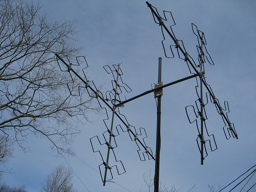
In order to gain some practical experience I did a quick weekend project and built a Fractal Quad antenna prototype for 10 meters based on an article written by Gary KF7BS (original 73 Magazine article here, pages 18-21). I used PVC tubes and other scrap materials I had available. I used the element dimensions in the KF7BS article but instead of aluminum wire I used #14/2 insulated copper wire as I had one 100ft roll available.
If you read different forum posts and discussions one of the reasons people dislike fractal antennas is the complexity of creating the fractal shape. In UHF frequencies you can simply etch the pattern on a small circuit board. However, in HF frequencies that approach does not work. I found that building fractal shape as described in the KF7BS article was not that hard. With PVC tube & standard 4 way / 3 way fittings readily available in Home Depot hardware store this was a piece of cake to put together. The article provides good tips how to construct the fractal shaped element. Here is how the element looks like:
I did a quick test with AIMUhf antenna analyzer to verify resonance frequency and impedance matching of the driver. Based on the measurement results I realized that the dimensions were a bit off as the resonance was at 27.3 Mhz instead of targeted 28.6 Mhz. This is probably due to the different diameter and velocity factor of the insulated #14 wire compared to #9 aluminum wire mentioned in the article. The fact that I measured this without the other element could also contribute to these results.
I built another element with about 5% shorter wire length. Initial measurement shows that this element is resonating at around 28.6 Mhz. I figured that I could use the first element as a reflector in a two element configuration without cutting / re-bending the wire.
![]() |
| Figure 1. Fractal Quad prototype for 28 Mhz |
I found many posts about fractal antennas in QRZ and eHam forums. I asked around in LinkedIn etc. for some practical designs as I wanted to learn more. Fractal antennas are mostly used in VHF/UHF frequencies. There is even a fractal antenna company nearby in Waltham founded by a ham - Chip Cohen W1YW. He has many patents on fractal antennas and has been innovating in this area since 1995. However, I have not seen many practical fractal antenna designs for HF bands and I have found no commercial fractal antennas for ham radio purposes.
In order to gain some practical experience I did a quick weekend project and built a Fractal Quad antenna prototype for 10 meters based on an article written by Gary KF7BS (original 73 Magazine article here, pages 18-21). I used PVC tubes and other scrap materials I had available. I used the element dimensions in the KF7BS article but instead of aluminum wire I used #14/2 insulated copper wire as I had one 100ft roll available.
If you read different forum posts and discussions one of the reasons people dislike fractal antennas is the complexity of creating the fractal shape. In UHF frequencies you can simply etch the pattern on a small circuit board. However, in HF frequencies that approach does not work. I found that building fractal shape as described in the KF7BS article was not that hard. With PVC tube & standard 4 way / 3 way fittings readily available in Home Depot hardware store this was a piece of cake to put together. The article provides good tips how to construct the fractal shaped element. Here is how the element looks like:
I did a quick test with AIMUhf antenna analyzer to verify resonance frequency and impedance matching of the driver. Based on the measurement results I realized that the dimensions were a bit off as the resonance was at 27.3 Mhz instead of targeted 28.6 Mhz. This is probably due to the different diameter and velocity factor of the insulated #14 wire compared to #9 aluminum wire mentioned in the article. The fact that I measured this without the other element could also contribute to these results.
I also found another link http://www.f3dd.org/mapage/index.html with some pictures of a fractal quad implemented for 14 Mhz band - - you can use google translator if you French skills are like mine. It looks like Bertrand F3DD bumped into this same problem. He was using 10/12 copper tube to build the elements. He made also the other element 5% shorter that became driver element. His page shows spacing of 2.77m so roughly 0.13 wavelength at 14.15Mhz between the driver and reflector elements. KF7BS article mentions that the original W1YW design was using 4.5 feet (1.37m) spacing which is 0.13 wavelength at 28.6 Mhz. That is probably a good starting point for the next step.
I used Kok Chen's (W7AY) CocoaNEC software for OSX to simulate the 2 element fractal quad for 28 Mhz. The simulation model I created using CocoaNEC does not seem to match exactly the actual prototype measurement results above, but this could be a problem with the model parameters or accuracy of the prototype dimensions. The measurements above were done on 10 ft mast off the ground and I did not have time to repeat measurements at different heights. Changing ground properties and antenna height in the NEC2 model does seem to have significant impact on the results, like with many other antennas.
I did also run simple optimization by changing parameters such as wire diameter, element distance (on 2 el quad), reflector vs. driver element size ratio, etc. to optimize SWR at target frequency of 28.6 Mhz. However, the F/B ratio even for the best models was less than 10 dB, so there is still some room for improvements.
![]() |
| NEC2 Model Output |
I got both reflector and driver elements finished, put a 4.5 ft boom in between and lifted the fractal quad prototype to the top of 28ft fiberglass mast (see Fig 1. ) The antenna analyzer measurement did show 1.2Mhz bandwidth ( SWR < 2.) from 27.994 Mhz to 29.198 Mhz.
I had the first test QSO with K6WR and did quick A/B testing comparing to my vertical antenna. K6WR operated a remote station in New Mexico and gave Fractal Quad 2-3 dB better signal report compared to the vertical antenna. I don't have a rotator yet and realized after the QSO that the antenna was sideways to him. I made few other contacts to Europe with varying results, mostly getting somewhat better signal results when using the 2 element Fractal Quad.
I wanted to get more factual data on how this antenna prototype performs against the vertical antenna I have used so far. I was running WSPR for few hours to get signal reports from multiple stations and switching between Fractal Quad and vertical antenna every 15 - 30 mins. Looking at the data from WSPR spots database I got about 75 reports from multiple stations 20 km - 5508 km distance from me. I plotted the SNR results by antenna model in use and by distance. This simple test did not provide any conclusive evidence - there was just too much SNR variation reported for both antennas. Perhaps the 10 m band conditions were changing too much as sun was setting in Europe?
So what did I learn about this small scale antenna experiment?
1) Antenna modeling software is a great tool when experimenting with new antennas. Without any previous exposure to antenna modeling I found software like CocoaNEC extremely useful to simulate different parameters, like height, element dimensions, spacing, etc. These tools are relatively easy to learn and understand. See also Beginner's Guide to modeling with NEC - a QST article series by L. B. Cebik, W4RNL (SK).
2) Testing the actual performance of the antenna requires quite a lot of work. I have AIMuhf vector impedance analyzer that is a great tool to measure the complex impedance, SWR and other antenna parameters quickly. However, to measure the actual radiation pattern and how the antenna performs in real world is a very complex topic. Using software like WSPR allows probing propagation paths around the world and with WSPRnet you can retrieve your signal-to-noise ratio as reported by multiple stations automatically. You can also use these tools for comparative antenna studies.
3) Building and testing antennas for ham radio purposes is a lot of fun. You can actually create something very concrete working just couple hours and - if experiment is successful - the antenna will improve your station performance significantly.
4) See also the eHam forum discussion for additional help & ideas on modeling and comparative testing.
73 de Mauri AG1LE
Subscribe to:
Posts (Atom)
Popular Posts
-
After reading many antenna articles in the Internet and a couple ARRL antenna books I got interested in physically small HF antennas. My b...
-
I have played with HDSDR and Elecraft KX3 for a while. While HDSDR is an excellent piece of software I am more familiar with PowerSDR as I...
-
INTRODUCTION In my previous post I created a Python script to generate training material for neural networks. The goal is to test how we...
-
Abstract I trained a Tensorflow based CNN-LSTM-CTC model with 5.2 hours of Morse audio training set (5000 files) and achieved charact...
-
REMOTE CONTROL OF ELECRAFT K3 I wanted to control my Elecraft KX3 transceiver remotely using my Android Phone. A quick Internet search yi...
-
MACHINE LEARNING CHALLENGE I was astonished to get email acknowledgement that my Kaggle Morse Challenge was approved today. I have spen...
-
Library of Congress, Prints & Photographs Division, FSA-OWI Collection While experienced CW operators can easily copy morse code f...
-
I had a 80 m dipole that was not performing too well because it was only at 25 ft height due to physical constraints in my backyard. Loo...
-
Inspired by "Ionic Fluid Antenna" article by N9ZRT David Hatch I started wondering whether human body could be used as an anten...
-
Introduction I have done some experiments with deep learning models previously. This previous blog post covers the new approach of buil...