After reading many antenna articles in the Internet and a couple ARRL antenna books I got interested in physically small HF antennas. My backyard is quite small and I don't have much space to hang up large HF antennas. The 80 meter dipole is about the largest I can fit within my property and even the dipole I have now is mounted a bit too low due to space constraints.
I found many posts about fractal antennas in QRZ and eHam forums. I asked around in LinkedIn etc. for some practical designs as I wanted to learn more. Fractal antennas are mostly used in VHF/UHF frequencies. There is even a fractal antenna company nearby in Waltham founded by a ham - Chip Cohen W1YW. He has many patents on fractal antennas and has been innovating in this area since 1995. However, I have not seen many practical fractal antenna designs for HF bands and I have found no commercial fractal antennas for ham radio purposes.
In order to gain some practical experience I did a quick weekend project and built a Fractal Quad antenna prototype for 10 meters based on an article written by Gary KF7BS (original 73 Magazine article here, pages 18-21). I used PVC tubes and other scrap materials I had available. I used the element dimensions in the KF7BS article but instead of aluminum wire I used #14/2 insulated copper wire as I had one 100ft roll available.

If you read different forum posts and discussions one of the reasons people dislike fractal antennas is the complexity of creating the fractal shape. In UHF frequencies you can simply etch the pattern on a small circuit board. However, in HF frequencies that approach does not work. I found that building fractal shape as described in the KF7BS article was not that hard. With PVC tube & standard 4 way / 3 way fittings readily available in Home Depot hardware store this was a piece of cake to put together. The article provides good tips how to construct the fractal shaped element. Here is how the element looks like:

I did a quick test with AIMUhf antenna analyzer to verify resonance frequency and impedance matching of the driver. Based on the measurement results I realized that the dimensions were a bit off as the resonance was at 27.3 Mhz instead of targeted 28.6 Mhz. This is probably due to the different diameter and velocity factor of the insulated #14 wire compared to #9 aluminum wire mentioned in the article. The fact that I measured this without the other element could also contribute to these results.

I built another element with about 5% shorter wire length. Initial measurement shows that this element is resonating at around 28.6 Mhz. I figured that I could use the first element as a reflector in a two element configuration without cutting / re-bending the wire.
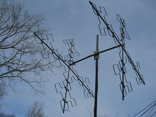 |
| Figure 1. Fractal Quad prototype for 28 Mhz |
I found many posts about fractal antennas in QRZ and eHam forums. I asked around in LinkedIn etc. for some practical designs as I wanted to learn more. Fractal antennas are mostly used in VHF/UHF frequencies. There is even a fractal antenna company nearby in Waltham founded by a ham - Chip Cohen W1YW. He has many patents on fractal antennas and has been innovating in this area since 1995. However, I have not seen many practical fractal antenna designs for HF bands and I have found no commercial fractal antennas for ham radio purposes.
In order to gain some practical experience I did a quick weekend project and built a Fractal Quad antenna prototype for 10 meters based on an article written by Gary KF7BS (original 73 Magazine article here, pages 18-21). I used PVC tubes and other scrap materials I had available. I used the element dimensions in the KF7BS article but instead of aluminum wire I used #14/2 insulated copper wire as I had one 100ft roll available.

If you read different forum posts and discussions one of the reasons people dislike fractal antennas is the complexity of creating the fractal shape. In UHF frequencies you can simply etch the pattern on a small circuit board. However, in HF frequencies that approach does not work. I found that building fractal shape as described in the KF7BS article was not that hard. With PVC tube & standard 4 way / 3 way fittings readily available in Home Depot hardware store this was a piece of cake to put together. The article provides good tips how to construct the fractal shaped element. Here is how the element looks like:

I did a quick test with AIMUhf antenna analyzer to verify resonance frequency and impedance matching of the driver. Based on the measurement results I realized that the dimensions were a bit off as the resonance was at 27.3 Mhz instead of targeted 28.6 Mhz. This is probably due to the different diameter and velocity factor of the insulated #14 wire compared to #9 aluminum wire mentioned in the article. The fact that I measured this without the other element could also contribute to these results.

I also found another link http://www.f3dd.org/mapage/index.html with some pictures of a fractal quad implemented for 14 Mhz band - - you can use google translator if you French skills are like mine. It looks like Bertrand F3DD bumped into this same problem. He was using 10/12 copper tube to build the elements. He made also the other element 5% shorter that became driver element. His page shows spacing of 2.77m so roughly 0.13 wavelength at 14.15Mhz between the driver and reflector elements. KF7BS article mentions that the original W1YW design was using 4.5 feet (1.37m) spacing which is 0.13 wavelength at 28.6 Mhz. That is probably a good starting point for the next step.
 |
| Source: http://www.f3dd.org/mapage/bv000012.jpg |
I used Kok Chen's (W7AY) CocoaNEC software for OSX to simulate the 2 element fractal quad for 28 Mhz. The simulation model I created using CocoaNEC does not seem to match exactly the actual prototype measurement results above, but this could be a problem with the model parameters or accuracy of the prototype dimensions. The measurements above were done on 10 ft mast off the ground and I did not have time to repeat measurements at different heights. Changing ground properties and antenna height in the NEC2 model does seem to have significant impact on the results, like with many other antennas.
I did also run simple optimization by changing parameters such as wire diameter, element distance (on 2 el quad), reflector vs. driver element size ratio, etc. to optimize SWR at target frequency of 28.6 Mhz. However, the F/B ratio even for the best models was less than 10 dB, so there is still some room for improvements.
 |
| NEC2 Model Output |
I got both reflector and driver elements finished, put a 4.5 ft boom in between and lifted the fractal quad prototype to the top of 28ft fiberglass mast (see Fig 1. ) The antenna analyzer measurement did show 1.2Mhz bandwidth ( SWR < 2.) from 27.994 Mhz to 29.198 Mhz.
I had the first test QSO with K6WR and did quick A/B testing comparing to my vertical antenna. K6WR operated a remote station in New Mexico and gave Fractal Quad 2-3 dB better signal report compared to the vertical antenna. I don't have a rotator yet and realized after the QSO that the antenna was sideways to him. I made few other contacts to Europe with varying results, mostly getting somewhat better signal results when using the 2 element Fractal Quad.
I wanted to get more factual data on how this antenna prototype performs against the vertical antenna I have used so far. I was running WSPR for few hours to get signal reports from multiple stations and switching between Fractal Quad and vertical antenna every 15 - 30 mins. Looking at the data from WSPR spots database I got about 75 reports from multiple stations 20 km - 5508 km distance from me. I plotted the SNR results by antenna model in use and by distance. This simple test did not provide any conclusive evidence - there was just too much SNR variation reported for both antennas. Perhaps the 10 m band conditions were changing too much as sun was setting in Europe?
So what did I learn about this small scale antenna experiment?
1) Antenna modeling software is a great tool when experimenting with new antennas. Without any previous exposure to antenna modeling I found software like CocoaNEC extremely useful to simulate different parameters, like height, element dimensions, spacing, etc. These tools are relatively easy to learn and understand. See also Beginner's Guide to modeling with NEC - a QST article series by L. B. Cebik, W4RNL (SK).
2) Testing the actual performance of the antenna requires quite a lot of work. I have AIMuhf vector impedance analyzer that is a great tool to measure the complex impedance, SWR and other antenna parameters quickly. However, to measure the actual radiation pattern and how the antenna performs in real world is a very complex topic. Using software like WSPR allows probing propagation paths around the world and with WSPRnet you can retrieve your signal-to-noise ratio as reported by multiple stations automatically. You can also use these tools for comparative antenna studies.
3) Building and testing antennas for ham radio purposes is a lot of fun. You can actually create something very concrete working just couple hours and - if experiment is successful - the antenna will improve your station performance significantly.
4) See also the eHam forum discussion for additional help & ideas on modeling and comparative testing.
73 de Mauri AG1LE


