I used TMP102 that is a digital sensor manufactured by Texas Instruments with I2C a.k.a. two wire interface (TWI) and the following features:
- 12-bit, 0.0625°C resolution
- Accuracy: 0.5°C (-25°C to +85°C)
- Low quiescent current
- 10µA Active (max)
- 1µA Shutdown (max)
- 1.4V to 3.6VDC supply range
- Two-wire serial interface
This is a very handy high resolution sensor that requires a very low current to operate.
There are quite many data logger boards available but only a few that are fully hack-able and small in size. I ended up selecting Sparkfun OpenLog board that looked small enough and that had all software, firmware and hardware designs available as open source. The only small problem was I2C (TWI) interface signals SCL and SDA. I had to solder wires directly to ATmega328 CPU pins, as they are not available on external interface. Soldering to surface mounted components requires steady hand and small soldering tip on your iron. Having a 20x optical microscope does also help.
Hardware components
The components for this project are listed below with links and cost at the time of writing this article. Most of these are available at Sparkfun.- Sparkfun OpenLog $24.95
- Digital Temperature Sensor Breakout - TMP102 $5.96
- Lithium Polymer USB Charger and Battery $24.95
- Samsung 16GB EVO Class 10 Micro SDHC $10.99
- Enclosure - 3D printed $9.50
Software Development
You can download the latest integrated software development environment from Arduino IDE page. I used the Arduino 1.5.8 with the following configuration- Tools/Board - Arduino Uno
- Tools/Port - /dev/ttyUSB0
To connect my Lenovo X301 laptop running Linux Mint 17 operating system I used FT231X Breakout with a Crossover Breakout for FTDI. To make it easier to connect I soldered Header - 6-pin Female (0.1", Right Angle) and
Break Away Male Headers - Right Angle connectors for these small breakout boards.
My focus in software development was to re-use existing OpenLog software, implement temperature measurement over I2C bus and try to minimize battery consumption by implementing power shutdown between measurements. This software is still works-in-progress but even with this software version (v3) the average current consumption is about 200 uA level @3.3 Volts. During measurement over I2C bus and when storing the results to the microSD card the current peaks to 25 mA for a few milliseconds.
The software makes a measurement every 5000 milliseconds. Since this design does not have a RTC chip the timekeeping is done with software. Software has a routine to compensate for timing errors but it is not very accurate yet. It meets my needs for data logging purposes for now. For the final product it might be useful to have RTC chip built into the design.
A fully charged 3.7 V 850mAh LiPo battery is estimated to provide power for this data logger over 170 days, though I haven't tested it for longer period than 15 days so far.
The latest logger software is posted in Github.
3D Printed Enclosure
I could not find a suitable small enclosure so I took OpenSCAD software into use and built a 3D model using some examples I found in Thingverse. OpenSCAD allows you to write 3D objects in simple language so it was quite easy to experiment with different designs and view them before creating the .STL file required for 3D printing.The enclosure size was determined mostly by the LiPo battery dimensions. With a smaller battery it would be possible to make a much smaller enclosure. Also, it would be possible to design a single circuit board with all the required components and make it smaller. Since this project is still in concept phase I chose to use the selected components and 3D print an enclosure where I can fit them in.
 |
| 3D model of enclosure |
I sent the .STL file to a local company with some email instructions. I my first version the dimensions were 1/8" units - this was not clear so I had to call them to clarify. In the 2nd version I used millimeters as units and the enclosure came out fabricated as I expected. The enclosure is big enough for the LiPo battery and it has also a small indention at the bottom to get the TMP102 sensor chip closer to the outside surface. The wall thickness was set to 1.0 mm and sensor chip is only 0.5 mm from the bottom surface.
The cover dimensions were designed it to be tightly fitted on the top.
 |
| 3D printed enclosure - top view |
 |
| 3D printed enclosure - side view |
Below is a photograph of 3D enclosure model v1 with wristbands attached.
 |
| 3D printed enclosure with wristbands attached |
In the photo below the hardware components fit in perfectly and the LiPo battery comes on the top. The power is connected using red and black wires to OpenLog board.
 |
| 3D printed enclosure with components inside |
Measurement Results
I tested the temperature logger by putting it from room temperature T0 22.6 °C into a freezer at Tm -21.0 °C.Based on the measurement results below (red graph) it took 54 minutes for the sensor to reach this temperature. The thermal mass of the sensor itself is small, but it was in a closed enclosure with the LiPo battery that has a much larger thermal mass. I did the same test but this time left the enclosure open so that the sensor was exposed to freezer temperature from both sides. The blue graph below shows that the sensor reached -21 °C in 30 minutes.
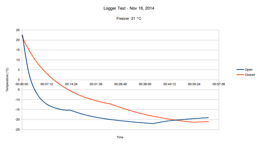 |
| Freezer Test |
The thermal time constant is defined as the time required by a sensor to reach 63.2% of a step change in temperature under a specified set of conditions.
The response of a sensor to a sudden change in the surrounding temperature is exponential and it is described by the following equation:
where T is sensor temperature, Tm is the surrounding medium temperature, T0 is the initial sensor temperature, t is the time and τ is the time constant.
Looking at the results above and trying to find best fit of measurement data to this model using RMS error method we can estimate that
τ = 0.009732 for closed enclosure
τ = 0.003132 for open enclosure
 |
| Model of thermal time constants τ |
In the datasheet there are the following guidelines to maintain accuracy.
The temperature sensor in the TMP102 is the chip itself. Thermal paths run through the package leads, as well as the plastic package. The lower thermal
resistance of metal causes the leads to provide the primary thermal path.
To maintain accuracy in applications requiring air or surface temperature measurement, care should be taken to isolate the package and leads from ambient air temperature. A thermally-conductive adhesive is helpful in achieving accurate surface temperature measurement.
One improvement would be to apply thermally-conductive materials between the sensor chip and the bottom surface of the enclosure. Some biologically inert metal like gold or titanium might provide better thermal time constant. Some insulation might be needed to isolate sensor from ambient air.
Conclusions
Temperature logging using modern, high resolution and accurate digital sensors is quite easy. You need only simple a micro-controller and few lines of code to build a data logger that is small enough to be wearable.Working with Arduinos is not only easy but also a lot of fun. With minimal investment you can build a powerful data logging device and add new sensors in incremental fashion. The software development is also straightforward and for most problems there is already some open source examples available.
The real challenges seem to be on the physics and mechanical enclosure design side. Building an enclosure for the sensor and electronics with a small thermal time constant is not trivial. For highly accurate wearable data logging devices you need also to consider many other topics such as
- physical appearance
- hypoallergic materials
- fit and comfort for different size of subjects
- thermal properties of materials
- any variability in sensor contact with subject or ambient air
It would be interesting to see the thermal design details of popular fitness trackers that claim accurate body temperature measurements. In particular the basal body temperature measurements where accuracy and high resolution is required poor thermal design would impact results significantly.


